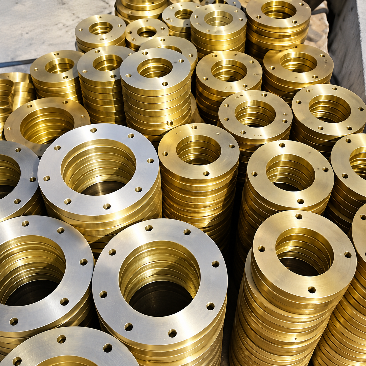
MS Slip On FlangeS
Mild steel slip-on flange product
Product Information

Common Specifications

Material, size range, standards, pressure ratings, available flange types and finish options.

Material
Mild Steel (MS)
Size Range
½″ to 48″
Standards
ANSI, DIN, BS, IS
Pressure Rating
150#, 300#, 600#
Types Available
Slip-On, Blind, Weld Neck, Threaded, Lap Joint, Socket Weld
Finish
Blackodised / Rust Preventive Coated
Mild Steel (MS) ½″–48″ ANSI / DIN / BS / IS 150# / 300# / 600#
Material Mild Steel (MS)
Size Range ½″ to 48″
Pressure Ratings 150#, 300#, 600#
Available Standards ANSI, DIN, BS, IS

Product Overview

Mild Steel Slip-On Flanges are piping components designed to fit over a pipe and form a bolted connection with a compatible flange or piping component. The pipe and flange are joined using the specified welding procedure.

Flange selection depends on the required nominal size, material grade, dimensional standard, pressure class, bolt drilling, facing, bore and operating conditions. These details should match the approved piping design.

Available configurations listed for this product range include Slip-On, Blind, Weld Neck, Threaded, Lap Joint and Socket Weld flanges. Confirm the exact type, dimensions and finish required for your order.

Technical Specifications

Material Mild Steel (MS)
Size Range ½″ to 48″
Standards ANSI, DIN, BS, IS
Pressure Ratings 150#, 300#, 600#
Types Available Slip-On, Blind, Weld Neck, Threaded, Lap Joint, Socket Weld
Finish Blackodised / Rust Preventive Coated
Facing Confirm the required facing and mating-flange compatibility in the order specification.
Bore To be selected according to the specified pipe dimensions and approved drawing.
Dimensions To be confirmed against the applicable standard and project specification.

Flange Size Chart

Technical note: The table below retains the dimensional values from the existing draft. Verify all dimensions, bolt counts and thicknesses against the applicable standard and approved drawing before manufacturing or procurement. The listed table does not provide rows for every size in the overall ½″ to 48″ range.
Nominal Pipe Size Pipe O.D. (mm) Flange O.D. (mm) Bolt Circle Dia. (mm) No. of Bolts Bolt Dia. (mm) Thickness (mm)
1/2″21.395.366.7412.74.8
3/4″26.7101.673.0412.74.8
1″33.4114.382.6412.74.8
1 1/4″42.2120.787.6412.76.4
1 1/2″48.3133.498.4412.76.4
2″60.3152.4114.3415.97.9
2 1/2″73.0165.1127.0415.97.9
3″88.9184.2146.1415.99.5
3 1/2″101.6203.2165.1415.99.5
4″114.3215.9177.8415.99.5
5″141.3254.0209.6815.912.7
6″168.3279.4228.6815.912.7
7″190.5304.8260.4815.912.7
8″219.1336.6292.1815.912.7
9″244.5368.3323.9819.115.9
10″273.0406.4355.6819.115.9
12″323.9457.2406.41219.115.9
14″355.6527.1469.91222.219.1
16″406.4577.9520.71222.219.1
18″457.2641.4584.21222.222.2
20″508.0704.9641.41622.525.4
24″609.6825.5755.71625.428.6
26″660.4889.0812.82028.631.8
28″711.2952.5876.32028.631.8
30″762.01016.0939.82431.835.0
32″812.81080.01003.32431.835.0
34″863.61143.01066.82831.838.0
36″914.41206.51130.32831.838.0

Standards, Materials & Flange Options

Standards

  • ANSI
  • DIN
  • BS
  • IS
  • Confirm the applicable standard for each order.

Material & Finish

  • Mild Steel (MS)
  • Blackodised finish
  • Rust preventive coated finish
  • Confirm available finish options before ordering.

Pressure Ratings

  • 150#
  • 300#
  • 600#
  • Verify the required pressure class and standard.

Slip-On Flange

  • Fits over the specified pipe
  • Welded pipe connection
  • Dimensions must match the selected standard.

Other Available Types

  • Blind
  • Weld Neck
  • Threaded
  • Lap Joint
  • Socket Weld

Dimensions & Fit

  • Nominal flange size
  • Outside diameter
  • Bolt circle and drilling
  • Thickness and bore
  • Confirm using the approved drawing.

Applications of MS Slip-On Flanges

Mild steel slip-on flanges can be used to connect compatible pipes and piping components in systems designed for the selected material, flange dimensions and service conditions.

The flange type, pressure class, standard, facing and dimensions should be checked against the piping design before selection. Actual suitability depends on the application and the approved engineering requirements.

Typical Application Areas

Water Pipelines HVAC Systems Utility Piping Industrial Piping Fire-Protection Systems

Flange Selection & Order Requirements

For accurate product selection, specify the nominal size, material, required standard, pressure class, flange type, drilling dimensions and finish. Share an approved drawing or technical specification wherever available.

✓Material: Mild Steel (MS)
✓Size: ½″ to 48″ range
✓Standard: ANSI, DIN, BS or IS
✓Pressure rating: 150#, 300# or 600#
✓Required flange type
✓Blackodised / rust preventive coated finish
✓Required bore and facing
✓Approved dimensions or technical drawing
Industrial Piping Components

MS Slip On Flanges

MS Slip On Flanges are mild steel piping components used to create flanged connections in compatible industrial piping systems. These flanges fit over the pipe and are welded according to the applicable design and installation requirements.

Selection depends on the required size, material grade, flange type, pressure requirements and applicable dimensional standard.

Mild Steel Multiple Size Options Industrial Piping

MS Slip On Flanges Specifications

Parameter Specification
Product NameMS Slip On Flanges
MaterialMild Steel (MS)
Size Range½″ to 48″, subject to configuration
StandardsANSI, DIN, BS and IS, as applicable
Pressure Options150#, 300# and 600#, subject to the applicable standard
Flange TypesSlip-On, Blind, Weld Neck, Threaded, Lap Joint and Socket Weld
FinishBlackodised / Rust Preventive Coated
ApplicationsCompatible industrial piping systems
Technical note: The listed sizes, pressure options, standards and flange types are product-range options, not necessarily one universal configuration. Confirm dimensions, drilling, material grade and pressure-temperature requirements for the selected product.

Features of MS Slip On Flanges

01

Mild Steel Construction

Designed for applications where the specified mild steel grade is suitable for the service conditions.

02

Multiple Sizes

The stated size range is ½″ to 48″. Confirm the dimensions and availability required for your project.

03

Finish Options

Blackodised and rust-preventive coated finishes are listed, subject to product confirmation.

Types of MS Flanges

Slip-On Flanges

Fit over a compatible pipe before welding. Dimensions and installation must follow the applicable flange standard.

Blind Flanges

Close a compatible piping end or cover a flanged opening in a piping system.

Weld Neck Flanges

Feature a tapered hub and are selected according to the piping design and applicable dimensional requirements.

Threaded Flanges

Use a threaded connection where permitted by the piping design and service conditions.

Lap Joint Flanges

Are used with compatible stub-end arrangements in piping systems designed for this connection.

Socket Weld Flanges

Are designed for compatible pipe connections using a socket arrangement and the specified welding procedure.

Applications of MS Slip On Flanges

MS Slip On Flanges may be used in compatible industrial piping applications where the material, flange design and operating conditions meet the project requirements.

  • Industrial and utility piping systems
  • Water-service piping, where material suitability is confirmed
  • HVAC and general-service piping
  • Manufacturing and process facilities
  • Connections to compatible industrial equipment

How to Select MS Slip On Flanges

Check these details before specifying or ordering flanges:

  • Nominal pipe size and actual pipe dimensions
  • Required flange type and connection arrangement
  • Applicable standard and dimensional specification
  • Required pressure class and design conditions
  • Material grade and corrosion-protection requirements
  • Facing, drilling, thickness and mating-flange compatibility
  • Operating pressure, temperature and service medium
Pressure class alone does not establish compatibility. The complete flange specification must match the piping system design.

Related Industrial Products

Explore related piping and flow-control products from Forex Valves for your industrial project.

Frequently Asked Questions

What are MS Slip On Flanges?

MS Slip On Flanges are mild steel piping components positioned over a compatible pipe and welded according to the applicable design and installation requirements.

What sizes are available?

The stated size range is ½″ to 48″. Confirm availability and dimensions for the selected flange standard and configuration.

Which standards are listed?

The listed standards include ANSI, DIN, BS and IS. The applicable standard depends on the selected flange configuration and project specification.

Which pressure options are listed?

The stated options are 150#, 300# and 600#. Verify the applicable standard, material, dimensions and design conditions before selection.

Which flange types are listed?

The listed types include Slip-On, Blind, Weld Neck, Threaded, Lap Joint and Socket Weld. Confirm availability for the required configuration.

Which finishes are listed?

The specified finish options are Blackodised and Rust Preventive Coated, subject to confirmation for the selected product.

What information is needed when ordering?

Provide nominal size, applicable standard, material grade, flange type, pressure requirements, facing, drilling, finish and quantity. Confirm the complete specification against the relevant catalogue or approved drawing.

MS Slip On Flanges — Product Information

Confirm the required size, standard, pressure specification, material grade, finish and quantity against the relevant catalogue or approved drawing before procurement.

Industrial Valve Solutions

Lined Diaphragm Valve Manufacturer and Supplier in India

Lined diaphragm valves are designed to control and isolate fluids in industrial processes where corrosion resistance, reliable shutoff and material compatibility are important. A flexible diaphragm regulates fluid flow, while a suitable internal lining helps protect the valve body from direct contact with process media.

✓
Corrosion Resistance Choose lining materials according to process media compatibility.
✓
Flow Isolation Diaphragm-based operation for controlling and isolating flow.
✓
Industrial Applications Suitable configurations depend on operating conditions and design.

What Is a Lined Diaphragm Valve?

A lined diaphragm valve is an industrial valve that uses a flexible diaphragm to control the movement of fluid through the valve. Its wetted surfaces are protected by a lining selected for compatibility with the process medium.

These valves are considered for applications involving corrosive chemicals, acids, alkalis and other process fluids. The suitable valve configuration depends on chemical concentration, temperature, pressure, flow requirements and the compatibility of the lining and diaphragm materials.

Material compatibility matters

The lining and diaphragm must be suitable for the actual process fluid and operating conditions. Confirm chemical compatibility and operating limits before selecting a valve.

How Does a Lined Diaphragm Valve Work?

A lined diaphragm valve operates through the movement of a flexible diaphragm against the valve's internal seating area. The actuator or handwheel moves a compressor or stem mechanism, which raises or lowers the diaphragm to regulate or stop fluid flow.

01

Opening

The diaphragm moves away from the seating area, allowing fluid to pass through the valve.

02

Flow Regulation

Diaphragm position changes the available flow passage, depending on valve design and operating conditions.

03

Closing

The diaphragm presses against the seating area to stop the flow when the valve is closed.

Main Components of a Lined Diaphragm Valve

The valve assembly combines the pressure-containing body, corrosion-resistant lining and diaphragm operating mechanism. Component materials and construction vary according to the valve model.

  • Valve body: Provides the main pressure-containing structure.
  • Internal lining: Helps isolate the body from the process medium.
  • Diaphragm: Opens, regulates or closes the flow passage.
  • Compressor and stem: Transfer movement from the operating mechanism.
  • Bonnet: Houses and protects the operating components.
  • Handwheel or actuator: Provides manual or automated operation, depending on configuration.

Lining Materials for Diaphragm Valves

Lining selection depends on chemical compatibility, operating temperature, pressure, permeation characteristics and the requirements of the process. Not every lining is suitable for every chemical or operating condition.

01

PTFE Lining

PTFE is used in applications where chemical resistance and low surface friction are important. Suitability depends on the specific service conditions.

02

PFA Lining

PFA lining is considered for demanding chemical services where the material's temperature and chemical-resistance characteristics are appropriate.

03

FEP Lining

FEP is another fluoropolymer option used in selected corrosive-fluid applications, subject to its rated operating limits.

04

PVDF Lining

PVDF may be considered for compatible chemical services. Confirm the chemical, temperature and pressure limits for the selected grade.

05

Rubber Lining

Suitable rubber compounds may be used for selected media. The exact elastomer must be checked against the fluid and operating conditions.

Applications of Lined Diaphragm Valves

Lined diaphragm valves may be used in industrial systems where fluid isolation, controlled flow and wetted-material compatibility are essential.

  • Chemical processing and chemical transfer systems
  • Acid and alkali handling, where material compatibility is confirmed
  • Pharmaceutical and specialty chemical processes
  • Water and wastewater treatment systems
  • Industrial process lines handling corrosive fluids
  • Other applications approved for the selected valve construction

Final suitability should be established using the process-fluid details, required flow conditions and the manufacturer's approved technical documentation.

Lined Diaphragm Valve Technical Specifications

The following table presents indicative specification categories for selection. Actual availability and ratings depend on the particular valve design and approved product documentation.

Specification Details
Valve Type Lined diaphragm valve
Lining Options PFA, FEP, PVDF or PTFE, subject to model availability
Size Range 1/2 inch to 6 inches (15–200 mm), to be confirmed
End Connection Flanged, according to the selected configuration
Pressure Rating Class 150 / PN16 references require model-specific confirmation
Temperature Range −20°C to +180°C, subject to material and design verification
Body Materials CI, CS, SS304, SS316, CF8, CF8M, CF3, CF3M, Duplex, Hastelloy or Monel, subject to availability
Service Media Compatible corrosive and industrial process fluids
Inspection and Testing API 598 / BS EN 12266 Part 1, where applicable to the specific product
Flange Standards DIN 2501 or ASME B16.5, depending on the selected configuration

Important: These values come from the supplied draft and have not been verified against an approved Forex Valves datasheet. Confirm the actual size range, pressure rating, temperature limits, materials and applicable standards before publishing these specifications as confirmed product capabilities.

How to Select the Right Lined Diaphragm Valve

Correct selection requires reviewing the process conditions and the valve's technical limits rather than choosing by size alone.

  1. Identify the process medium: Confirm the chemical composition, concentration and compatibility requirements.
  2. Check operating temperature: Select a lining and diaphragm rated for the actual operating range.
  3. Confirm pressure requirements: Match the valve's approved pressure rating to the system design.
  4. Determine the required size: Consider line size, flow rate and pressure drop requirements.
  5. Choose body and lining materials: Confirm wetted-material compatibility for the application.
  6. Verify connections and standards: Check flange dimensions, applicable standards and testing requirements.
  7. Review operating requirements: Decide whether manual or actuated operation is needed.

Lined Diaphragm Valve vs Lined Ball Valve

Both valve types can be used in selected corrosive-fluid applications, but their operating mechanisms and flow-control characteristics differ.

Lined Diaphragm Valve

  • Uses a flexible diaphragm to control flow.
  • Often selected where diaphragm-based isolation is suitable.
  • Diaphragm material and service limits must be checked.
  • Available operating configurations depend on the product design.

Lined Ball Valve

  • Uses a rotating ball with a flow passage.
  • Commonly operated through a quarter-turn mechanism.
  • Selection depends on lining, seats, seals and operating conditions.
  • Flow and shutoff performance depend on the valve design.

The appropriate valve depends on the process requirements, material compatibility, operating conditions and approved product specifications.

Installation and Maintenance Considerations

Proper installation and routine inspection help maintain valve operation and identify wear or damage. Always follow the manufacturer's instructions for the exact model.

  • Verify the flow direction and installation orientation where specified.
  • Inspect the lining, diaphragm and sealing surfaces before installation.
  • Use suitable gaskets, fasteners and flange-tightening procedures.
  • Avoid exposing the valve to pressure or temperature conditions outside its approved limits.
  • Inspect for leakage, diaphragm wear and visible lining damage.
  • Isolate and depressurize the system before inspection or maintenance.
  • Replace worn components using compatible, approved parts.

Lined Diaphragm Valve Manufacturer and Supplier in India

Forex Valves provides industrial valve solutions for process applications. When evaluating a lined diaphragm valve for a specific installation, buyers should confirm the available valve configuration, body and lining materials, size, pressure rating, temperature limits and inspection requirements.

Sharing the process medium and operating conditions helps establish whether a particular valve configuration is appropriate for the intended service.

Frequently Asked Questions

1. What is a lined diaphragm valve used for?

It is used to control or isolate compatible process fluids, including selected corrosive media, in industrial applications.

2. Which lining materials are available?

PTFE, PFA, FEP and PVDF are potential lining options, depending on the product design and confirmed availability.

3. How do I choose the correct lining material?

Consider the process fluid, concentration, operating temperature, pressure and compatibility information provided for the material.

4. Can a lined diaphragm valve handle every corrosive chemical?

No. Compatibility depends on the chemical and its operating conditions. Confirm the lining and diaphragm compatibility before selection.

5. What details should I provide when requesting a valve?

Provide the process medium, line size, operating pressure, temperature, required end connection and any applicable project standards.

Looking for a Lined Diaphragm Valve?

Contact Forex Valves with your application details to discuss the required valve configuration, lining compatibility and technical specifications.

CONTACT FOREX VALVES